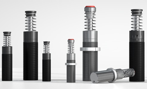
ACE provides the right shock absorber for every industrial purpose. Over 200 different models are available, from the smallest model with a 4 mm stroke up to the biggest with 406 mm.
Whether self-compensating or adjustable, with ACE dampers between 0.68 Nm/cycle and 126,500 Nm/cycle can be absorbed and effective weights between 500 g and 204 t can be decelerated with great precision.
In addition, ACE damping solutions impress with competent consulting, exemplary service and ideal matching accessories.
Your advantages using industrial shock absorbers
- Safe, reliable production
- Long service life of the machines
- Easy, inexpensive constructions
- Low operating costs
- Quiet, economical machines
- Less stress on the machine
- Profit improvement
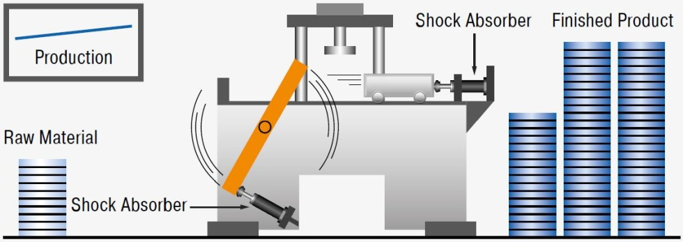
PICTURE: STOPPING WITH INDUSTRIAL SHOCK ABSORBERS
Results using conventional dampers
- Loss of production
- Machine damage
- Increased maintenance costs
- Increased operating noise
- Higher machine construction costs
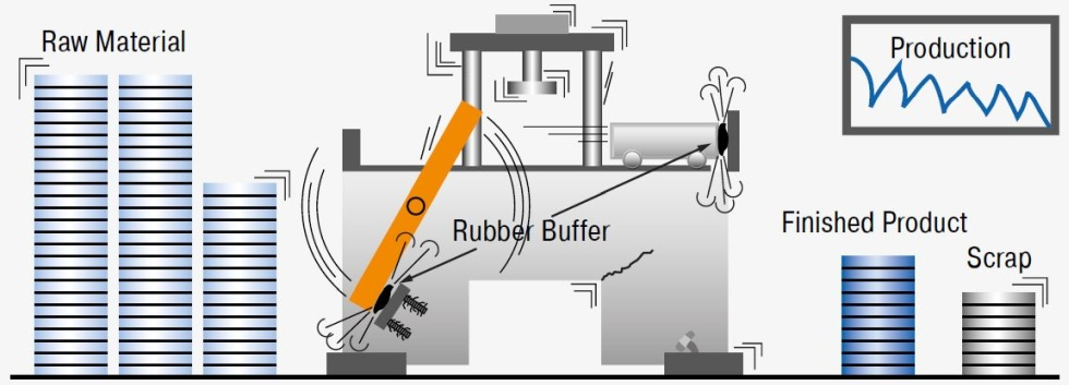
PICTURE: STOPPING WITH RUBBER BUFFERS, SPRINGS, DASHPOTS OR CYLINDER CUSHIONS
Comparison of Different Damping Elements
When it comes to slowing down moving masses with constant damping force through the stroke, the industrial shock absorber is the right choice. A comparison demonstrates the differences of the damping elements.
ACE Industrial Shock Absorbers (Uniform stopping force through the entire stroke)
The moving load is smoothly and gently brought to rest by a constant resisting force throughout the entire shock absorber stroke. The load is decelerated with the lowest possible force in the shortest possible time eliminating damaging force peaks and shock damage to machines and equipment. This is a linear deceleration force stroke curve and is the curve provided by ACE industrial shock absorbers. In addition they considerably reduce noise pollution.
Hydraulic Dashpot (High stopping force at start of the stroke)
With only one metering orifice the moving load is abruptly slowed down at the start of the stroke. The braking force rises to a very high peak at the start of the stroke (giving high shock loads) and then falls away rapidly.
Springs and Rubber Buffers (High stopping forces at end of stroke)
At full compression. Also they store energy rather than dissipating it, causing the load to rebound back again.
Air Buffers, Pneumatic Cylinder Cushions (High stopping force at end of stroke)
Due to the compressibility of air these have a sharply rising force characteristic towards the end of the stroke. The majority of the energy is absorbed near the end of the stroke.
Comparison
The comparison shows the differences of the damping in a direct comparison of stopping force to stopping stroke:
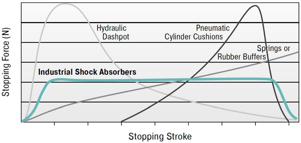
PICTURE: STOPPING FORCE OVER TIME
General Function of the Pressure Chamber
If a moving mass hits the industrial shock absorber, the piston puts the oil in the pressure chamber into motion. The oil is pressed through the metering orifices, which converts the discharged energy into heat. The metering orifices are arranged on the stroke so that the mass is retarded with a constant damping force. The hydraulic pressure is maintained throughout the entire braking process nearly constant.
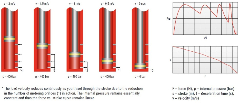
PICTURE: PRINCIPLE OF THROUBLE DRILL BORINGS FOR SHOCK DAMPERS INCLUDING FUEL TRAIN DIAGRAM
How do I adjust a shock absorber correctly?
If an adjustable shock absorber is set too soft or too hard, it can cause shocks and damage to your machine. To prevent this, the following video shows you how to optimally adjust an adjustable shock absorber to your application.
Parallel mounting of two shock absorbers
If the shock absorber cannot be mounted centrally, it is advisable to mount two dampers in parallel. It is very important that they are installed exactly parallel. The following video visualises the installation process and explains further requirements:
Mounting in rotary applications
The following video gives a detailed explanation of what you have to consider when installing ACE industrial shock absorbers in rotary applications:
